Demystify how traffic reaches directly to pod on using alb.ingress.kubernetes.io/target-type: ip

In the above screenshot, you can see that the AWS Load Balancer Controller provides 2 ways to send traffic to the pod.
1. instance: The Kubernetes way where via nodePort LB sends traffic to the POD
ALB ->NodePort -> ClusterService (Iptables managed by kube-proxy)->Pod
2. IP: The AWS way using the “VPC CNI plugin”.
Alb -> Pods
Now the question, how VPC CNI plugin bypasses the Kubernetes way???

You guess it right! by using IPAMD. It creates a network interface and assigns eni to the node with secondary Ip addresses. These IPs are assigned to the pods. This is how AWS bypasses the Kube-proxy and sends traffic directly to the pod.
This was about incoming traffic, but what about outgoing traffic??
CNI plugin creates SNAT rules in IPtables on the host machine so that pod can communicate to the outer world.
Note: I am only covering traffic outside VPC. There are other scenarios as well where the pod communicates to other pods running on the same or different node. If you want to have insight into these, let me know and I will be happy to demystify that for you.
Further, I tested this on public instance.
Enough for the overview. Now let's try to understand things practically in nutshell. You can follow me along.
Pre-requisite:
- Assuming, you have an ec2 running (amazon Linux) with secondary eni with additional Ip. If you do not have an instance, you can refer.
- ssh login of the instance.
- public ec2 machine.
- Required whitelisting in the security group to check internet connectivity from the instance.
- A cup of coffee and smile :-)
Steps:
Install the following packages:
# yum install nc telnet nsenter iptables-services -yWe will be listening on a port using nc and try to connect using telnet. Iptables will be used for SNAT.
Create a network namespace and inside that, we will be assigning IP to the interface and then listen on that IP and a port. We are trying to mimic a pod here.
###
Create virtual interface named veth0 and veth1
#### ip link add veth0 type veth peer name veth1###
Create namespace named vnet0 and set the veth0 with namespace. Note: after adding link set, you won't see veth0 on host machine.
#### ip netns add vnet
# ip link set veth0 netns vnet0###
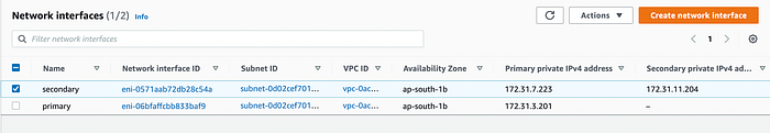
Verify the veth1 and eth1. Make sure secondary IP should not be there on eth1. If it is there, you need to remove the IP using "ip addr del 172.31.11.204/20 dev eth1"
#### ip a
1: lo: <LOOPBACK,UP,LOWER_UP> mtu 65536 qdisc noqueue state UNKNOWN group default qlen 1000
link/loopback 00:00:00:00:00:00 brd 00:00:00:00:00:00
inet 127.0.0.1/8 scope host lo
valid_lft forever preferred_lft forever
inet6 ::1/128 scope host
valid_lft forever preferred_lft forever
2: eth0: <BROADCAST,MULTICAST,UP,LOWER_UP> mtu 9001 qdisc pfifo_fast state UP group default qlen 1000
link/ether 0a:7a:6a:ee:bc:34 brd ff:ff:ff:ff:ff:ff
inet 172.31.3.201/20 brd 172.31.15.255 scope global dynamic eth0
valid_lft 3489sec preferred_lft 3489sec
inet6 fe80::87a:6aff:feee:bc34/64 scope link
valid_lft forever preferred_lft forever
3: veth1@if4: <BROADCAST,MULTICAST,UP,LOWER_UP> mtu 1500 qdisc noqueue state UP group default qlen 1000
link/ether 12:fa:5d:42:9c:9c brd ff:ff:ff:ff:ff:ff link-netns vnet0
inet6 fe80::10fa:5dff:fe42:9c9c/64 scope link
valid_lft forever preferred_lft forever
5: eth1: <BROADCAST,MULTICAST,UP,LOWER_UP> mtu 9001 qdisc pfifo_fast state UP group default qlen 1000
link/ether 0a:5d:69:b0:f9:6e brd ff:ff:ff:ff:ff:ff
inet 172.31.7.223/20 brd 172.31.15.255 scope global dynamic eth1
valid_lft 3002sec preferred_lft 3002sec
inet6 fe80::85d:69ff:feb0:f96e/64 scope link
valid_lft forever preferred_lft forever
###
Assign IP to the interface. You can replace the IP with your secondary IP. I am using the Secondary private IPv4 of secondary interface.
#### ip -n vnet1 addr add 172.31.11.204/32 dev veth0###
Bring up the vnet1 interface
#### ip -n vnet1 link set eth1 up
# ip -n vnet1 link set lo up###
confirm that the interfaces are up
#### ip netns exec vnet0 ip addr show1: lo: <LOOPBACK,UP,LOWER_UP> mtu 65536 qdisc noqueue state UNKNOWN group default qlen 1000
   link/loopback 00:00:00:00:00:00 brd 00:00:00:00:00:00
    inet 127.0.0.1/8 scope host lo
       valid_lft forever preferred_lft forever
    inet6 ::1/128 scope host
       valid_lft forever preferred_lft forever
4: veth0@if3: <BROADCAST,MULTICAST,UP,LOWER_UP> mtu 1500 qdisc noqueue state UP group default qlen 1000
   link/ether 86:b0:f8:b2:36:0c brd ff:ff:ff:ff:ff:ff link-netnsid 0
    inet 172.31.11.204/32 scope global veth0
       valid_lft forever preferred_lft forever
    inet6 fe80::84b0:f8ff:feb2:360c/64 scope link
       valid_lft forever preferred_lft forever
Setup connectivity between the host interface and virtual interface. Execute the below commands inside the vnet0 namespace.
###
Gateway IP '169.254.1.1' will be mapped with 'veth1@if4' mac address '12:fa:5d:42:9c:9c' in the ARP table as static entry
#### ip netns exec vnet0 ip route add 169.254.1.1 dev veth0 scope link
# ip netns exec vnet0 ip route add default via 169.254.1.1 dev veth0
# ip netns exec vnet0 arp -i veth0 -s 169.254.1.1 12:fa:5d:42:9c:9c###
verify arp entry
#### ip netns exec vnet0 arp -a
? (169.254.1.1) at 12:fa:5d:42:9c:9c [ether] PERM on eth0###
verify route table
#### ip netns exec vnet0 ip route show
default via 169.254.1.1 dev eth0
169.254.1.1 dev eth0
On the host side, we need to configure the routes for vnet0 (veth0) interface IP.
###
Add rules for the routing table
#### ip rule add from all to 172.31.11.204 lookup main prio 512
# ip rule add not from all to 172.31.0.0/16 lookup main prio 1025
# ip rule add from 172.31.11.204 lookup 10001 prio 1536###
Check all the rules are in place, this is the important part where we are specifying rules to route traffic.
512: from all to 172.31.11.204 lookup main. used for traffic to the pod
1536: from 172.31.11.204 lookup 10001  used for traffic from the pod.
1025: not from all to 172.31.0.0/16 lookup main, used for internet traffic
#### ip rule
0: from all lookup local
512: from all to 172.31.11.204 lookup main
1025: not from all to 172.31.0.0/16 lookup main
1536: from 172.31.11.204 lookup 10001
32766: from all lookup main
32767: from all lookup default###
Add the route of veth0 IP in the main route table
#### ip route add 172.31.11.204 dev veth1###
added the route for veth1 and IP inside vnet0. This vnet behaves like a pipe for communication veth1 -> veth0
#### ip route show
default via 172.31.0.1 dev eth0
169.254.169.254 dev eth0
172.31.0.0/20 dev eth0  proto kernel  scope link  src 172.31.3.201
172.31.11.204 dev veth1 scope link# ip route show table 10001
default via 172.31.0.1 dev eth1
172.31.0.0/20 dev eth1 proto kernel scope link src 172.31.7.223###
Enable IP forwarding on the host machine
#### sysctl net.ipv4.ip_forward=1
That is all for the incoming traffic setup to the namespace vnet. Let us test this now.
Open a new terminal and move inside the namespace
###
To enter into the namespace, type exit inside the terminal once you are inside vnet0 if you want to do anything on host machine. Else, you may always open up new terminal.
#### nsenter --net=/var/run/netns/vnet0###
try some ping to self and IP of eth0 interface.
#### ping 172.31.11.204
PING 172.31.11.204 (172.31.11.204) 56(84) bytes of data.
64 bytes from 172.31.11.204: icmp_seq=1 ttl=64 time=0.044 ms
64 bytes from 172.31.11.204: icmp_seq=2 ttl=64 time=0.045 ms
64 bytes from 172.31.11.204: icmp_seq=3 ttl=64 time=0.043 ms# ping 172.31.3.201
PING 172.31.3.201 (172.31.3.201) 56(84) bytes of data.
64 bytes from 172.31.3.201: icmp_seq=1 ttl=64 time=0.044 ms
64 bytes from 172.31.3.201: icmp_seq=2 ttl=64 time=0.045 ms
64 bytes from 172.31.3.201: icmp_seq=3 ttl=64 time=0.043 ms###
Start nc with 172.31.11.204 and port 80
#### nc -l 172.31.11.204 80 -v###
Open a new terminal and try telneting 172.31.11.204 on port 80
#### telnet 172.31.11.204 80
Trying 172.31.11.204...
Connected to 172.31.11.204.
Escape character is '^]'.
We are all good to receive traffic on 172.31.11.204 from other ec2 instances as well. You can try this by yourself. Just run another instance and do the needful whitelisting and try connecting to 172.31.11.204.
WAIT, we have not checked the outgoing traffic.. right? Let’s do that
# nsenter --net=/var/run/netns/vnet0
# ping google.comPING google.com (172.217.160.206) 56(84) bytes of data.
^C
--- google.com ping statistics ---
2 packets transmitted, 0 received, 100% packet loss, time 1015ms:-(
Seems like this is not working!! Sit back and relax as we have not configured anything for outgoing traffic. No more wait, let’s configure this and bring this POC to the end.
Create the following iptable rules on the host machine and make sure the iptables should be up and running. You may type ‘exit’ to come out of the namespace.
###
Rules
delete reject from input.. you need to check the rule number before deleting. For me, it was 5.
###iptables -D INPUT 5###
Create the following chains. This is what AWS does
###iptables -N AWS-SNAT-CHAIN-1 -t nat
iptables -N AWS-SNAT-CHAIN-0 -t nat###
Create the SNAT rule, here please note that the IP '172.31.3.201' is the primary IP of my primary interface. When I was writing this blog, I found it mandatory that wecan't put any other interface or secondary IP here as SNAT.
#### iptables -t nat -A AWS-SNAT-CHAIN-1 -m addrtype ! --dst-type LOCAL -j SNAT --to-source 172.31.3.201 --random-fully# iptables -t nat -A AWS-SNAT-CHAIN-0 ! -d 172.31.0.0/16 -j AWS-SNAT-CHAIN-1# iptables -t nat -A POSTROUTING -j AWS-SNAT-CHAIN-0
###
List Iptable rules
###
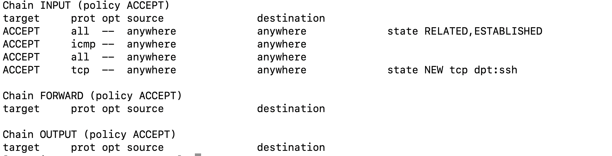
# iptables -L
iptables -L -t nat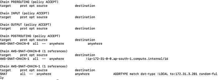
And we are done with outbound rules. Let’s test the implementation.
# ping google.comPING google.com (172.217.160.206) 56(84) bytes of data.64 bytes from bom07s16-in-f14.1e100.net (172.217.160.206): icmp_seq=1 ttl=50 time=1.66 ms
64 bytes from bom07s16-in-f14.1e100.net (172.217.160.206): icmp_seq=2 ttl=50 time=1.79 ms
64 bytes from bom07s16-in-f14.1e100.net (172.217.160.206): icmp_seq=3 ttl=50 time=1.76 ms
64 bytes from bom07s16-in-f14.1e100.net (172.217.160.206): icmp_seq=4 ttl=50 time=1.74 ms
64 bytes from bom07s16-in-f14.1e100.net (172.217.160.206): icmp_seq=5 ttl=50 time=1.75 ms
64 bytes from bom07s16-in-f14.1e100.net (172.217.160.206): icmp_seq=6 ttl=50 time=1.74 ms
64 bytes from bom07s16-in-f14.1e100.net (172.217.160.206): icmp_seq=7 ttl=50 time=1.76 ms^C--- google.com ping statistics ---7 packets transmitted, 7 received, 0% packet loss, time 6011ms
rtt min/avg/max/mdev = 1.668/1.747/1.798/0.048 ms# curl google.com<HTML><HEAD><meta http-equiv="content-type" content="text/html;charset=utf-8">
<TITLE>301 Moved</TITLE></HEAD><BODY>
<H1>301 Moved</H1>
The document has moved
<A HREF="http://www.google.com/">here</A>.
</BODY></HTML>
Done and dusted !!
I hope you have not found this difficult to set up. I have tried to simplify the networking of EKS using AWS CNI and wanted to help people in understanding the functionality. If I missed something or any step requires further explanation, do let me know I will try to unfold that as well.
References:
Looking at Amazon EKS through a networking lens
Elastic Network Interface
Setting up Namespace
AWS VPC CNI proposal
What is SNAT